There has never been anything like the Saturn V, the launch vehicle that powered the United States past the Soviet Union to a series of manned lunar landings in the late 1960s and early 1970s. The rocket redefined "massive," standing 363 feet (110 meters) in height and producing a ludicrous 7.68 million pounds (34 meganewtons) of thrust from the five monstrous, kerosene-gulping Rocketdyne F-1 rocket engines that made up its first stage.
At the time, the F-1 was the largest and most powerful liquid-fueled engine ever constructed; even today, its design remains unmatched (though see the sidebar, "The Soviets," for more information on engines that have rivaled the F-1). The power generated by five of these engines was best conceptualized by author David Woods in his book How Apollo Flew to the Moon—"[T]he power output of the Saturn first stage was 60 gigawatts. This happens to be very similar to the peak electricity demand of the United Kingdom."
Despite the stunning success of the Saturn V, NASA's direction shifted after Project Apollo's conclusion; the Space Transport System—the Space Shuttle and its associated hardware—was instead designed with wildly different engines. For thirty years, NASA's astronaut corps rode into orbit aboard Space Shuttles powered by RS-25 liquid hydrogen-powered engines and solid-propellant boosters. With the Shuttle's discontinuation, NASA is currently hitching space rides with the Russians.
But there's a chance that in the near future, a giant rocket powered by updated F-1 engines might once again thunder into the sky. And it's due in no small part to a group of young and talented NASA engineers in Huntsville, Alabama, who wanted to learn from the past by taking priceless museum relics apart... and setting them on fire.
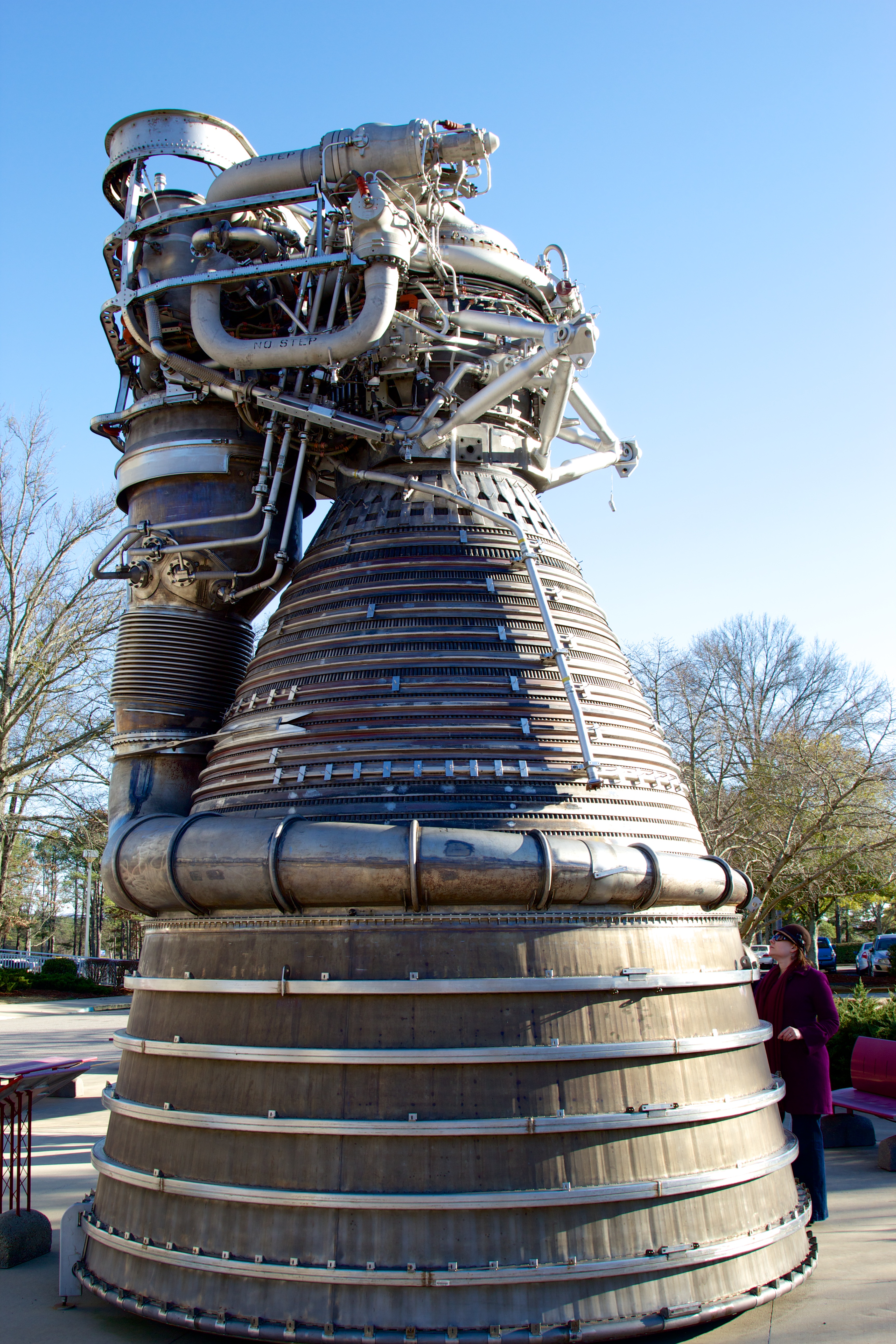
An F-1 engine on display at NASA's Marshall Space Flight Center. Author's wife at right for scale.
Enter our young rocket scientists
Tom Williams is the kind of boss you want to have. He's smart, of course—that's a prerequisite for his job as the director of the NASA Marshall Space Flight Center's (MSFC) Propulsion Systems Department. But he doesn't mind stepping back and giving his team interesting challenges and then turning them loose to work out the details. Case in point: NASA's Space Launch System (SLS), intended to be an enormous heavy-lift system that will rival the Saturn V in size and capabilities. In thinking about propulsion for the SLS, NASA for the first time in thirty years is considering something other than solid rocket boosters.
The decision to use a pair of solid rocket boosters for the Space Shuttle instead of liquid-fueled engines like the F-1 had been partly technical and partly political. Solid fuels are hugely energy dense and provide an excellent kick to get a spacecraft moving off of the ground; also, selecting solid fuel boosters allowed the government to send some available contracting dollars to companies involved with building intercontinental ballistic missiles, leveraging that expertise and providing those companies with additional work.
But solid boosters have several downsides, including an inability to stop combustion. Without pumps to switch off or valves to close, solid boosters work a lot like the "morning glory" sparklers my dad used to buy on the Fourth of July—once lit, they burn until they're done. Solid rocket booster design decisions, specifically in regard to containing combustion, contributed to the destruction of the Space Shuttle Challengerand the death of its crew (thoughChallenger's destruction was more a failure of NASA management than of technology).
Still, as the Space Shuttle program drew to a close and potential successors came and went, the inertia of solid boosters and the facilities and people that produced them ensured that they remained a part of the plans.
SLS gave NASA the chance to do a total rethink. As design studies got underway, Williams realized it might be a good idea to re-familiarize the MSFC Propulsion Systems Department with huge kerosene gas generator engines like the F-1 (referred to in shorthand as "LOX/RP-1" or just "LOX/RP" engines, after their oxidizer and fuel mixture of liquid oxygen and RP-1kerosene). Scale aside, the F-1 is conceptually a relatively simple design, and that simplicity could translate into cost reduction. Reducing cost for space access is a key priority—perhaps even theoverriding priority—outside of safety.
There was a problem, though. SLS' design parameters called for a Saturn V-scale vehicle, capable of lifting 150 metric tons into low Earth orbit. No one working at MSFC had any real experience with gigantic LOX/RP-1 engines; nothing in the world-wide inventory of launch vehicles still operates at that scale today. So how do you make yourself an expert in tech no one fully understands?
Nick Case and Erin Betts, two liquid engine systems engineers working for Williams, found a way. Although no launch vehicles that used F-1 engines are still around, actual F-1s do exist. Fifteen examples sit attached to the three Saturn V stacks on display at NASA facilities, including MSFC; dozens more are scattered around the country on display or in storage. Williams' team inspected the available engines and soon found their target: a flight-ready F-1 which had been swapped out from the launch vehicle destined for the to-be-canceled Apollo 19 mission and instead held in storage for decades. It was in excellent condition.
Case and Betts spearheaded the paperwork-intensive effort to requisition the F-1 from storage and get it into their workshop. They were aided by R.H. Coates, a more senior member of Williams' team and lead propulsion engineer for the SLS Advanced Development Office. Williams offered encouragement and assistance from the management side, but the team was otherwise given free rein on how to proceed. After some study, they came to Williams with a request that was pure engineer: "Why don't we just go ahead and take this thing apart and see what makes it work?"
Williams said yes. "It allowed some of our young engineers to get some hands-on experience with the hardware," he told me, "what we would term the 'dirty hands' approach to learning, just like you did when you took apart your bicycle when you were a kid, or your dad's lawnmower or his radio. One of the best ways to learn as an engineer, or in anything, is to take it apart, study it, ask questions."
And then, hopefully, build a better one.
The plans! The plans!
The F-1 teardown started in relatively low-key fashion. As the team dug into the engine, it became obvious that the internal components were in good shape. In fact, though there was some evidence of rainwater damage, the engine overall was in great shape.
The team initially wanted to build an accurate computer model of every component in the engine so that its behavior could be modeled and simulated, but another goal soon began to take shape: maybe, just maybe, they could mount some of the engine components on a test stand and make the F-1 speak again after 40 years.
Why was NASA working with ancient engines instead of building a new F-1 or a full Saturn V? One urban legend holds that key "plans" or "blueprints" were disposed of long ago through carelessness or bureaucratic oversight. Nothing could be further from the truth; every scrap of documentation produced during Project Apollo, including the design documents for the Saturn V and the F-1 engines, remains on file. If re-creating the F-1 engine were simply a matter of cribbing from some 1960s blueprints, NASA would have already done so.
A typical design document for something like the F-1, though, was produced under intense deadline pressure and lacked even the barest forms of computerized design aids. Such a document simply cannot tell the entire story of the hardware. Each F-1 engine was uniquely built by hand, and each has its own undocumented quirks. In addition, the design process used in the 1960s was necessarily iterative: engineers would design a component, fabricate it, test it, and see how it performed. Then they would modify the design, build the new version, and test it again. This would continue until the design was "good enough."
Further, although the principles behind the F-1 are well known, some aspects of its operation simply weren't fully understood at the time. The thrust instability problem is a perfect example. As the F-1 was being built, early examples tended to explode on the test stand. Repeated testing revealed that the problem was caused by the burning plume of propellent rotating as it combusted in the nozzle. These rotations would increase in speed until they were happening thousands of times per second, causing violent oscillations in the thrust that eventually blew the engine apart. The problem could have derailed the Saturn program and jeopardized President Kennedy's Moon landing deadline, but engineers eventually used a set of stubby barriers (baffles) sticking up from the big hole-riddled plate that sprayed fuel and liquid oxygen into the combustion chamber (the "injector plate"). These baffles damped down the oscillation to acceptable levels, but no one knew if the exact layout was optimal.
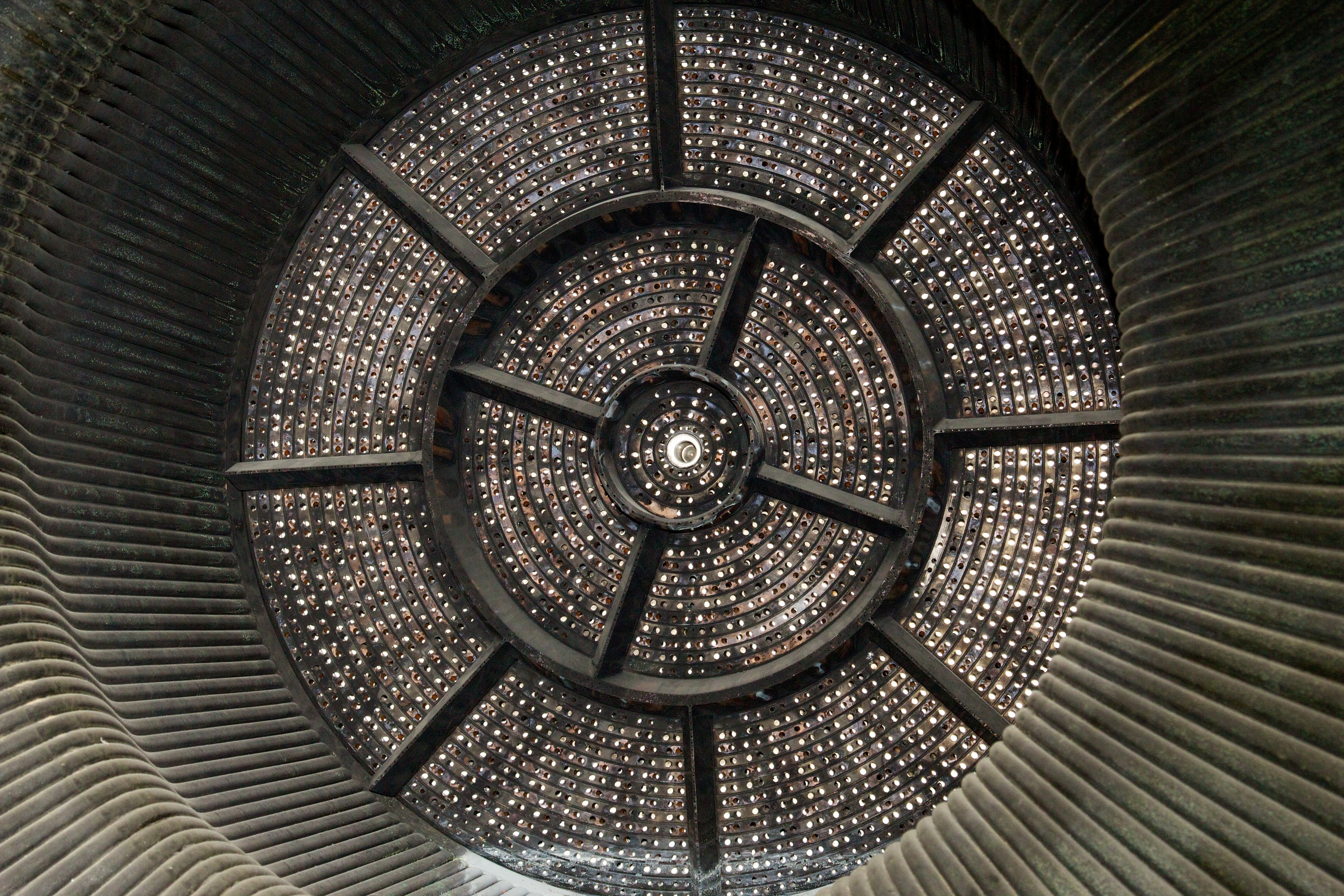
Detail on an F-1 engine injector plate at the forward end of the nozzle. Fuel and liquid oxygen are sprayed out of these holes under tremendous pressure, with each ring alternating propellant and oxidizer.
The baffle arrangement "was just a trial and error thing," explained Senior Propulsion Engineer R.H. Coates. "But we'd like to model that and say, well, what if you took one of those baffles out?" Because the baffles are mounted directly to the injector plate, they take up surface area that would otherwise be occupied by more injector holes spraying more fuel and oxidizer; therefore, they rob the engine of power. "So if you want to up the performance on this thing, we can evaluate that with modern analytical techniques and see what that does to your combustion stability."
But before any "hot-fire" testing could occur, the team had to take the very physically real F-1 engine and somehow model it. It's easy—well, relatively easy—to turn a set of CAD files into a real product. Turning a real product into a set of CAD files, though, requires a bit of ingenuity, especially when that product is a gigantic rocket engine.
To tackle the task, NASA brought in a company called Shape Fidelity, which specializes in a technique called "structured light scanning." If you don't have access to the laser from TRON, structured light scanning is just about the next best way to cram something inside of a computer.
Firing my laser
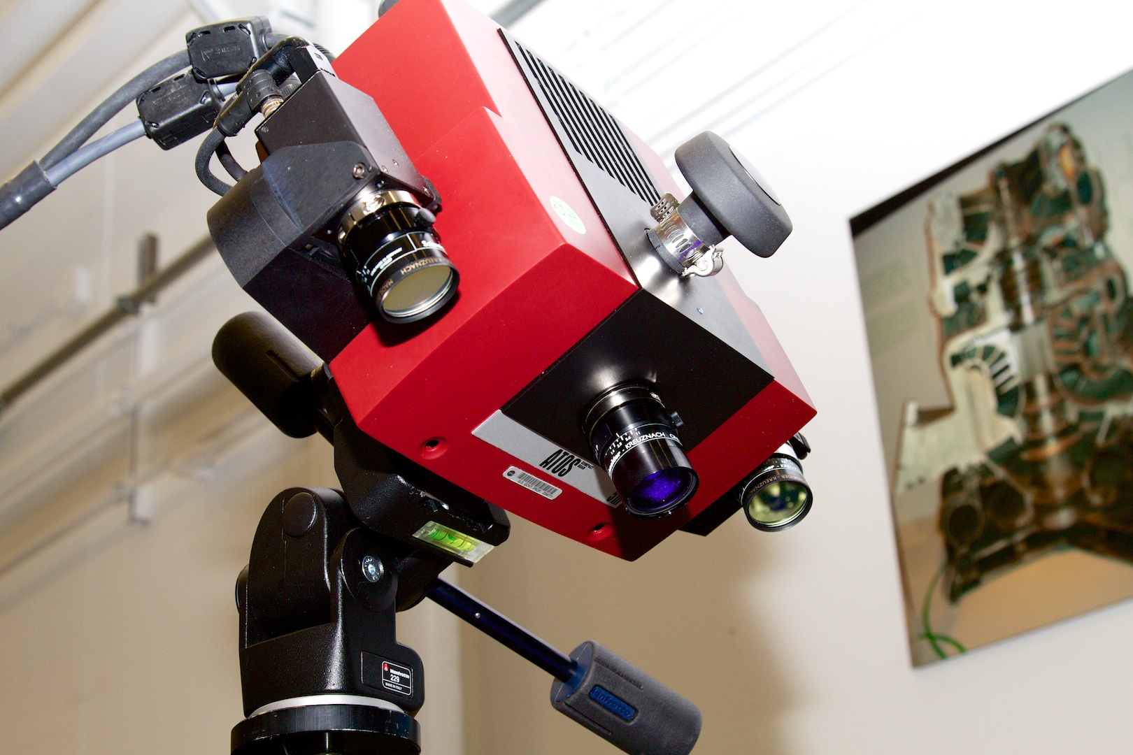 The structured light scanner assembly. The middle lens is the projector, and the outer two lenses are cameras that look at how the projector's light falls onto the surface being scanned.
The exterior of the F-1 was meticulously photographed and then mapped with a structured light scanning rig, which uses a projector to paint a pattern of stripes onto the surface being scanned. Mounted on the side of the projector are two cameras which each record how the pattern falls on the surface being scanned. For every exposure, the projectors and camera capture sixteen different stripe patterns.
The structured light rig can focus on an area ranging from 65mm in size all the way out to 1.5 meters, so getting a surface scan of the entire F-1 engine required a lot of crawling around and manually aiming the scanner rig. It wasn't immediately obvious how a bunch of handheld scan images could maintain coherency—how do you indicate to the scanner that picture 2 is linked to picture 1?
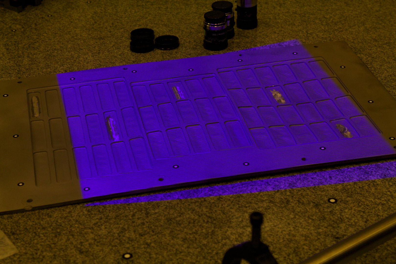
Scanning a small object with the structured light scanner. The alternating horizontal bars in the purple projection are used by the cameras to detect surface detail. Note positional decals around the object's perimeter.
The answer was both simple and brilliant. "You notice these little targets? These little stickers?" said Shape Fidelity engineer Rob Black, who was demonstrating the equipment for me. Black indicated the small white-on-black circular dots pasted on the test material on the table in front of us. All around us were disassembled F-1 engine pieces, and I noticed that every single component was peppered with the little dots. "We stick these things on by hand, and the scanner sees these targets, so when we move from one position to the next, it can see what's coming... and stitch everything together. That way, we don't have to use encoders or robots."
Each part gets tiny dots hand-applied in what is effectively a random, unique pattern. The structured light software can use the unique layout of dots to stitch together all pictures of the object being scanned, without requiring the camera to be mounted in a motion controlled rig.
"We took just a regular digital camera and walked around the engine and took photographs," Black said. "The software took all those photographs and built a 3D coordinate for each of the targets, and what you get is a very sparse data set—it's basically the X-Y-Z value of the center of these points."
 The rough point-cloud assembled by the structured light scanning application, using the black and white positional dot stickers.
After the point map was assembled, Black performed a detailed structured light scan of the entire outside surface of the engine. "But what we wanted was a scan of the inside—the vanes, the clearances, all the definition of the interior," explained Black.
Taking the F-1 apart to get at its insides was always part of the plan, but as the team proceeded, it became obvious that actually cracking the thing open without breaking it was going to require specialized tooling—tooling that might have existed 40 years ago but which has long since been destroyed or lost.
The exterior scan was therefore used to develop the specialized tooling needed to fit the F-1's nuts, bolts, and fasteners. Some of the bolts were annoyingly unique—Betts noted that at least one high-torque bolt in the turbopump assembly required its own special torque adapter to remove.
 Detail structured light scan model, showing connectors against which custom tooling needed to be manufactured.
The team was able to use the structured light scan of that particular bolt and, in less than half a day, to fabricate a tool using an additive manufacturing method called electron beam melting to quickly "print" 3D projects out of metal powder. Armed with this and other custom tools, Case, Betts, and Coates took the engine apart, down to its tiniest components.
"So what that let us do was scan the parts—all the individual pieces and parts," Black said. He pulled up a PowerPoint presentation on his laptop and pointed at one particular slide. "This is an example of one of the scanned pieces. You'll notice the gray is the scanned data, like we got on the screen here, but it also maps to points. Well, those points are the same points that were mapped in the assembly [the initial scan]. There's only one way that part will fit into that constellation of points, and that's what you see on the lower right."
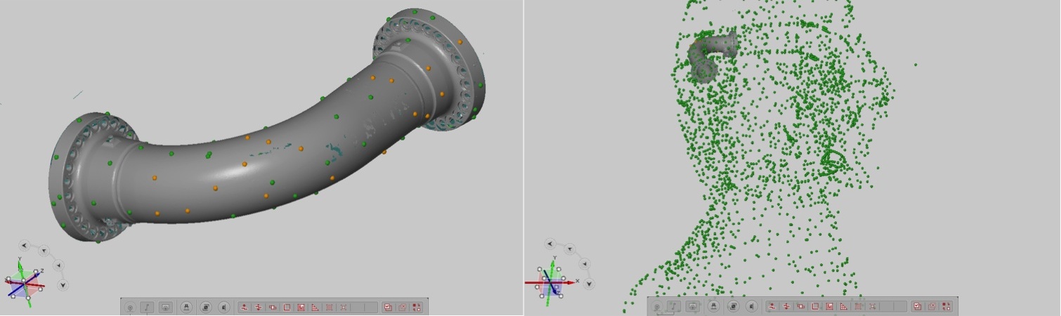 The randomly placed dots are left on each part's surface as it is scanned inside and out. After scanning, the computer fits the now highly detailed part back into the model, using the arrangement of its surface stickers as a guide.
"And so what you get now is a true 3D definition, inside and out, of all the relationships—not just the part geometry, but the relationship between the parts. And we did this for all the parts that you see on the shelves here," Black added.
Touching the past

The final composite model, accurate inside and out, made up of all the rocket's thousands of pieces carefully fitted together.
The result was a complete and highly accurate CAD model of the entire F-1 rocket engine, down to its tiniest bolt. The fidelity was so good that the scanner even picked up tiny accumulations of soot left on the turbine blades from the engine's previous test firing back in the 1960s. The engineers removed the soot and re-scanned, but even this seemingly trivial accumulation yielded valuable data—sooting is a problem with kerosene-powered engines, so understanding how it builds up inside the engine could reduce its occurrence.
"Because they didn't have the analytical tools we have today for minimizing weight, everything was very robust," noted Betts, when I asked what they found as they tore down the engine. "That's apparent in really every aspect of the engine. The welds—"
"Oh, the welds!" interrupted Case. "The welds on this engine are just a work of art, and everything on here was welded." The admiration in his voice was obvious. "Today, we look at ways of reducing that, but that was something I picked up on from this engine: just how many welds there were, and howgreat they looked."
F-1 turbopump exhaust manifold, showing expert hand-done welding.
"You look at a weld that takes a day," he continued, "and there are thousands of them. And these guys were pumping engines out every two months. It's amazing what they could do back then and all the touch labor it took."
"Their ability to withstand imperfection, too," said Betts. "There were a few things on the engine that we disassembled, where today you may throw that part away because of the imperfections, but it goes to show that they fully understood what the big drivers were in their design. That's one thing we were trying to get knowledge on: what imperfections were OK to live with versus what imperfections are going to give us problems?"
"Like with the injector," said Case, speaking of the 44-inch (1.1 meter) metal plate that spewed the propellent into the engine's nozzle. "There are hundreds of holes drilled into the main injector—all drilled by hand, too. And one of the holes you can actually see where the drill bit came down at the wrong spot, and the guy just stopped—you can see where he moved over to where the hole was supposed to be and finished drilling the hole. They kept that and would have flown with that engine. Those kinds of things were pretty neat."
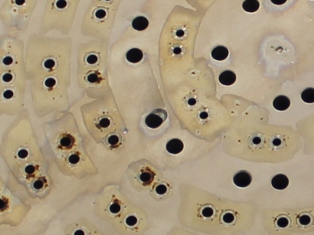
Close-up of the rear of an F-1 engine injector plate. Note mis-drilled injector hole at center.
"One thing I notice when I look back at older engines," commented Coates, the senior engineer, "was just like Nick and Erin were alluding to: the complexity of the welds. You didn't have the kind of advanced manufacturing we had today, so quite honestly, these were hand-made machines. They were sewn together with arc welders, and it's pretty amazing to see how smooth and elegant it came out. Today, you'd look at doing precision casting, not these thousands of welds."
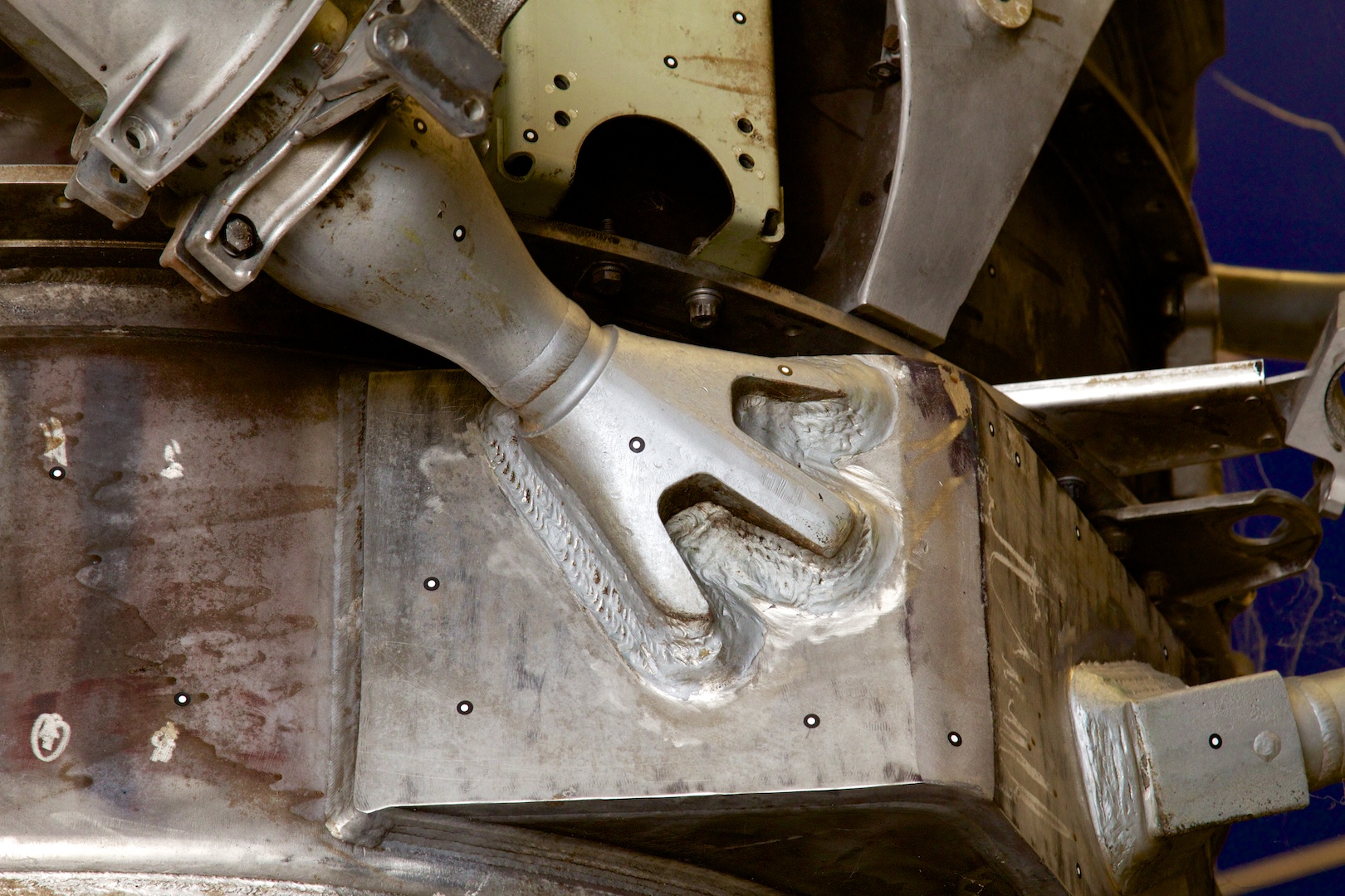
Connection point of an F-1's gimbal (one of three), showing a huge amount of welding.
Lighting a 40-year old candle
The engine disassembled by Betts, Case, and Coates was number F-6090, assembled in December 1968 just as Apollo 8 was carrying three astronauts further away from Earth than any human being had ever before traveled. F-6090 had been test-fired for 240 seconds and then mounted on the S-IC stage of the Saturn V that would have flown as Apollo 19, but the engine was eventually pulled and placed into storage at MSFC. As the team methodically stripped engine F-6090 down, it became obvious that a test-fire of some of the engine's components was within the realm of probability.
With F-6090 being torn apart to learn from, the team turned to engine F-6049, which had served for years as a display engine at the Udvar-Hazy Center at the Smithsonian National Air and Space Museum. F-6049 was in even better condition than F-6090, but simply firing the entire F-1 engine straight away wasn't practical. For one thing, though the F-1s were originally tested at MSFC in the 1960s, that test infrastructure has since been repurposed. In addition, the city of Huntsville has grown up considerably since the Apollo era; lighting off an engine the size of an F-1 at Marshall today would likely blow out every window in the entire city.
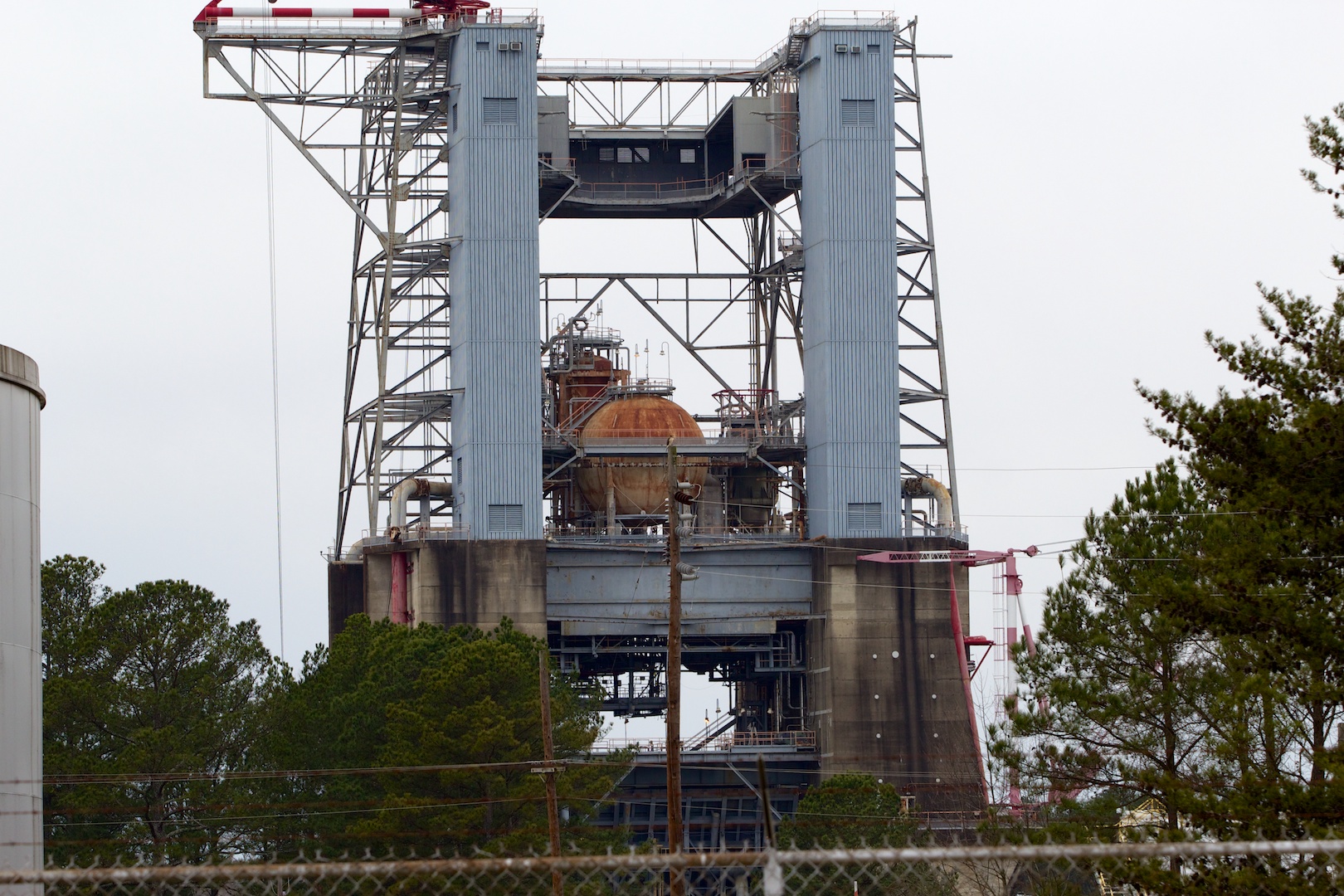
The test stand used for the F-1 engine firing in the 1960s has been repurposed many times since then. Retrofitting it for use with an F-1 engine again would be cost-prohibitive... and the test would blow out every window in Huntsville.
Instead, the team decided to start with a series of firings on F-6049's gas generator. An engine like the F-1 is sort of like two separate rocket engines: one small, one large. The smaller one consumes the same fuel as the larger, but its rocket exhaust is not used to lift the vehicle; instead, it drives the enormous turbopump that draws fuel and oxidizer from the tanks and forces them through the injector plate into the main thrust chamber to be burned.
As with everything else about the F-1, even the gas generator boasts impressive specs. It churns out about 31,000 pounds of thrust (138 kilonewtons), more than an F-16 fighter's engine running at full afterburner, and it was used to drive a turbine that produced 55,000 shaft horsepower. (That's 55,000 horsepower just to run the F-1's fuel and oxidizer pumps—the F-1 itself produced the equivalent of something like 32 million horsepower, though accurately measuring a rocket's thrust at that scale is complicated.)
Getting the gas generator ready for firing would be a huge step in teaching Betts and Case about LOX/RP-1 engines, and it would provide modern data on just how well the old components operate. Betts, Case, and Coates pulled the gas generator, the gas generator injector, and the gas generator combustion chamber from F-6049, along with one of the ball valves for the propellent. Every "soft good" in the gas generator—every seal and gasket—had to be recreated from scratch, since all had hardened or rotted. In the process, the team had to spend quite a bit of time ensuring that they were creating functional seals and gaskets, since plastics technology had changed considerably since the 1960s. Just creating the soft goods required a lot of chemistry work.
As the preparation for the gas generator tests continued, though, something happened that caused the exercise to shed its academic roots and turn very, very practical.
Rocketdyne returns
NASA's SLS will most likely be a multi-stage vehicle, with boosters attached to its first "core" stage, but NASA is holding a competition to determine whether those boosters will be fueled by solid or liquid propellent. The Advanced Booster competition has finally brought liquid-fueled contenders into a space dominated for decades with solid fuel boosters built by a company called ATK.
One of the companies selected to compete for the Advanced Booster contract is Dynetics, a 1,300-employee company headquartered in Huntsville, near MSFC. Dynetics has primarily done work for the Department of Defense, but within the past five years it has expanded into aerospace. It's one of three companies proceeding into the design phase of the contract, and it might have a secret weapon: Dynetics is partnered with Pratt & Whitney Rocketdyne (PWR), and its entry into the booster competition will be powered by an enormous LOX/RP-1 engine called the F-1B (based on the F-1 and its uprated but never flown F-1A variant).
The F-1 gas generator tests that Betts, Case, and Coates were preparing for were set to happen at an extremely opportune time: their exploratory work on the F-1 started near the end of 2012, right around the time Dynetics was selected as a competitor for the Advanced Booster contract. Dynetics had an absolutely golden opportunity; right down the street, NASA was about to start test-firing an F-1 gas generator, something that hadn't been done in decades.
Through a complex set of letters of agreement, MSFC allowed Dynetics and PWR engineers to use the resurrected gas generator and engine test facilities. The engineering effort even included cooperation with heritage Rocketdyne engineers in California and Huntsville—folks who were involved in the original design and testing of the F-1 and who had engineering expertise and advice to contribute to the effort. MSFC conducted 11 hot-fire tests of the gas generator, ranging from 5 to 30 seconds each, with Dynetics and PWR representatives present and assisting.
After Dynetics and its Pratt & Whitney Rocketdyne subcontractor worked out the agreements and paper, the company needed to run its own set of tests on the F-1 gas generator to gather additional data beyond what Betts, Case, and Coates had gleaned. This necessitated a second series of gas generator test firings in the latter half of February, so Ars headed out to Huntsville to watch.
Watching the test
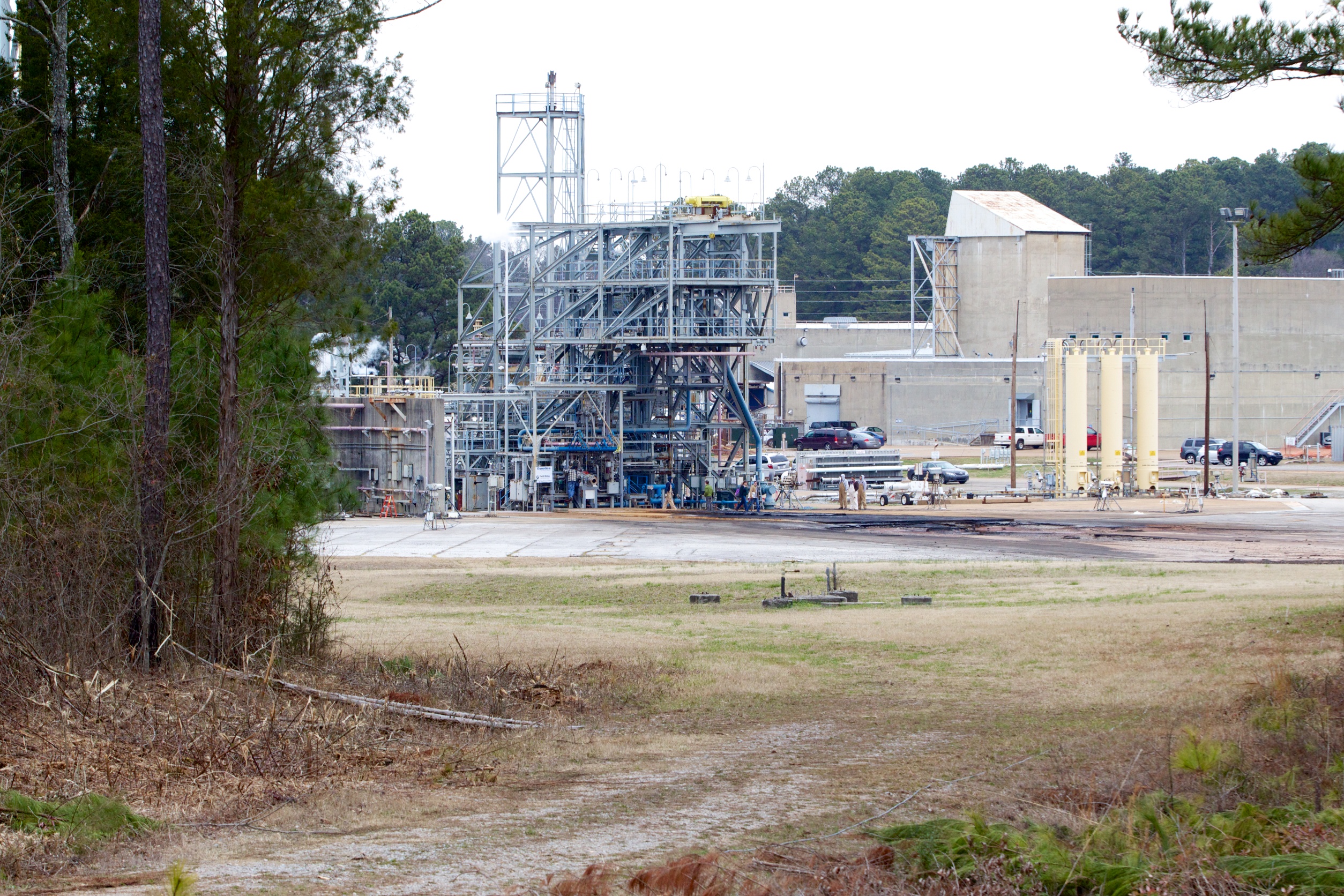
On the morning of February 20 I found myself perched on a set of metal bleachers under an iron-gray Huntsville sky, with the thermometer reading 33ºF—quite a bit cooler than this Texas boy is used to enduring, especially since the wind wouldn't stop gusting. The payoff was that the observation area sat only a short distance from the gas generator test stand. Through a clearing in a row of evergreens and scrub, separated from us by a dirt path, I saw the test stand itself: a jungle-gym pile of metal and pipes, with personnel scurrying around to make last-minute adjustments.
The view from the bleachers, looking at the gas generator test stand.
The gas generator test firing I was there to witness was neither the first nor the last, but it still drew a hefty crowd of folks—civil servants, family members, and no small number of Dynetics/PWR employees. As the clock ticked down toward firing, we packed ourselves into the rickety bleachers and the buzz of conversation gradually quieted; I focused on holding my camera steady and trying not to touch any of the exposed metal of the heavy (and freezing) telephoto lens.
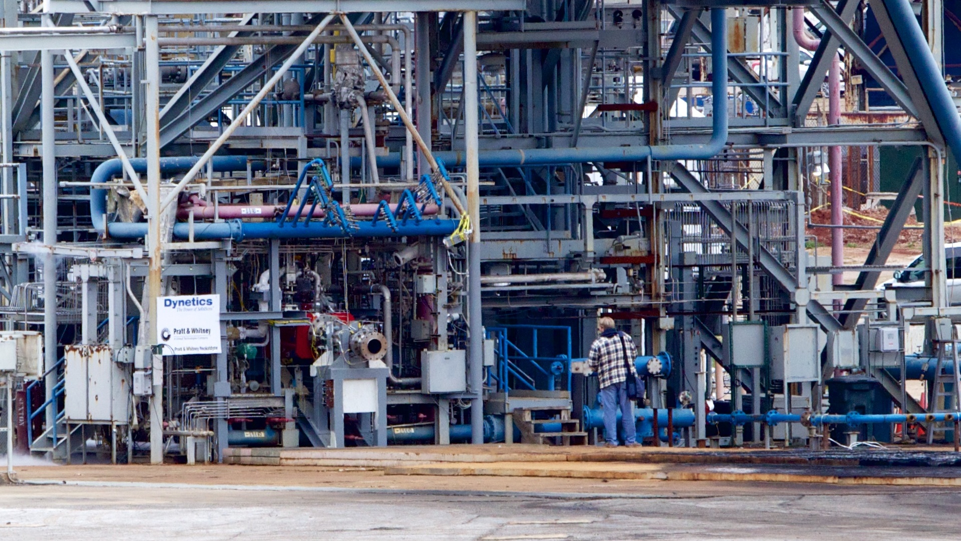 Engine F-6049's gas generator mounted on the hot-fire test stand prior to firing (with test personnel setting things up still visible). The gas generator itself isn't really visible—it's mounted behind the red thrust take-up plate.
The blast, when it came, was loud without being overwhelming. We were close enough that there wasn't more than a quarter second's delay between the flash and the sound, and I felt the warmth of burning kerosene exhaust roll over me. The gas generator spoke with a deep rumbling, topped with a rocket's crackle-crackle-crackle—a sound I'd always thought was just the microphone clipping when listening to recordings of rocket launches. The overall noise of the thing was impressive—probably about as loud as a loud rock concert—but we were far enough away not to need hearing protection. The gas generator produced a long horizontal column of flame, which held steady for the entire test. It was impressive, but it was even more impressive when I reminded myself that in a real F-1 all this fire and noise and smoke was merely used to drive the machinery that fed fuel into the engine for the realfireworks.
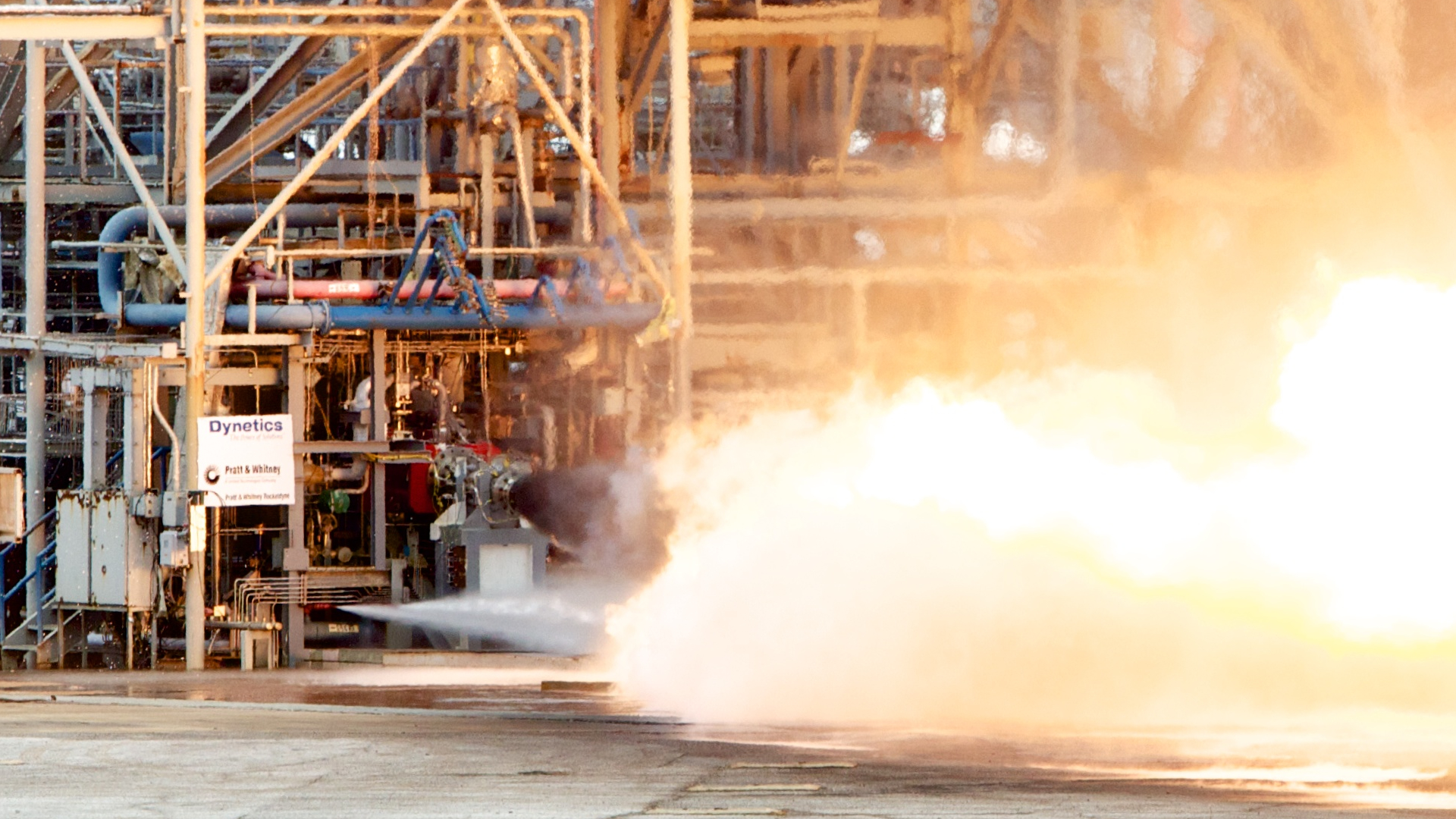
The gas generator firing. Visible emerging from the nozzle is the dark, fuel-rich exhaust, which takes a bit of time to completely burn. This is characteristic of gas generator exhausts.
After perhaps fifteen seconds, the exhaust wavered and went out, and enormous clouds rose around the test area. Sprinklers had been spraying the stand throughout the test, and the water from those sprinklers was now noisily transforming itself into steam. The assembled crowd applauded, muffled claps rising from hands which were mostly gloved or mittened against the chill.
3D printing goes to space
The Dynetics advanced booster itself—tentatively codenamed Pyrios, after one of the fiery horses that pulled the god Apollo's chariot—typifies the "big dumb booster" design. The booster's construction will be as efficient and minimal as possible, using simple 3/4-inch (1.9cm) aluminum barrel segments friction-stir welded together over the propellant tanks. One advantage of using RP-1 as a fuel is that it doesn't need heavy thermal protection—it won't boil off at sea level pressure and temperature like liquid hydrogen does. (The Pyrios booster concept might have to include some external thermal protection for the liquid oxygen tankage.)
Even though the performance goals of the engine will be close to its predecessor, its manufacturing will be done through radically different methods. The Dynetics folks echoed Betts, Case, and Coates when reflecting on the F-1's construction, making many of the same observations about the jaw-dropping amount of hand-done work in the old design. In the name of affordability and efficiency, modern manufacturing techniques will be brought firmly to bear on the new version.
Each Pyrios booster will feature a pair of F-1B engines, built with techniques that more resemble 3D printing than traditional casting or milling. The main combustion chamber and nozzle in particular will undergo tremendous simplification and consolidating; the parts count for those two assemblies together will be reduced from 5,600 manufactured elements in the original F-1 down to just 40.
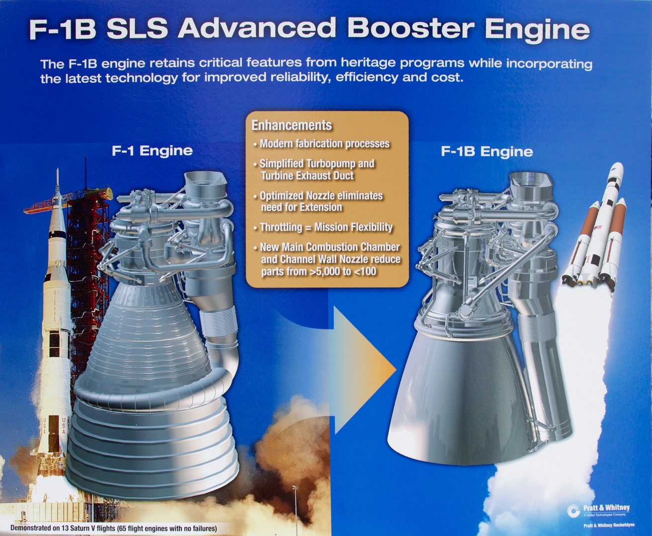
Photo of the F-1/F-1B comparison chart Dynetics/PWR had on display at the test firing, showing several key differences between the F-1 and F-1B.
Using state of the art manufacturing processes where possible actually reduces cost—even if a newer manufacturing method is more expensive, the cost reductions gained from the design simplifications more than tip the scales. In particular, Dynetics and PWR are using techniques like selective laser melting and hot isostatic pressing (HIP) to "grow" entire complex engine parts out of metal powders. The Dynetics team is focusing as much as possible on reducing welds and joins, and therefore reducing assembly and manufacturing.
(We've got lots more on Dynetics and their F-1B-powered Pyrios booster in this companion piece.)
Engineers and their engines
After the test-firing, Betts, Case, and Coates showed me around the MSFC lab where the F-1 disassembly effort was still underway. We stopped in to visit engine F-6049, mounted up on its trolly with its gas generator conspicuously missing. I crawled all over the thing while the trio of engineers talked about the big old machine with which they'd become so familiar.
"These guys came up with the idea," said Tom Williams, gesturing toward Betts and Case, "that LOX/RP looks like something we need to get smart on again, so how about we take apart one of these?" The two engineers were standing next to the F-6049, along with Coates. "These guys started thinking how to go about it and got the structured light guys into it, but it was just a small group of engineers who got the idea to get their hands dirty."
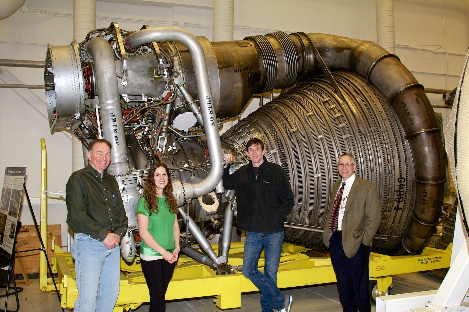
The team that brought the F-1 back to life. From left: R.H. Coates, Erin Betts, Nick Case, and manager Tom Williams. Behind them is engine F-6049. Its gas generator would normally occupy the space just above and to the right of Betts' head—note the white covering in place where the gas generator's exhaust would feed into the turbopump.
That's engineering at its finest. The disassembly and hot fires have yielded a tremendous amount of data, and the Dynetics/PWR team is in the midst of turning that data into a practical, usable engine. There are plans later this year to mate the gas generator back to its pumps and turbines, recreating the F-1's entire "powerpack" (the entire engine except for the combustion chamber). The powerpack will then be tested at NASA's Stennis Space Center in Mississippi. It's not much of a leap after that to a completed engine.
The Advanced Booster competition runs at least another two years, with a final decision expected in 2015 or 2016. Solid fuel remains a major contender—possibly the front-runner—but the Pyrios booster does stand a real chance of thundering past its competitors.
When NASA's SLS rocket flies, she may well be drawn into the sky by Apollo's fiery steed.
No comments:
Post a Comment
Let us know your Thoughts and ideas!
Your comment will be deleted if you
Spam , Adv. Or use of bad language!
Try not to! And thank for visiting and for the comment
Keep visiting and spread and share our post !!
Sharing is a kind way of caring!! Thanks again!